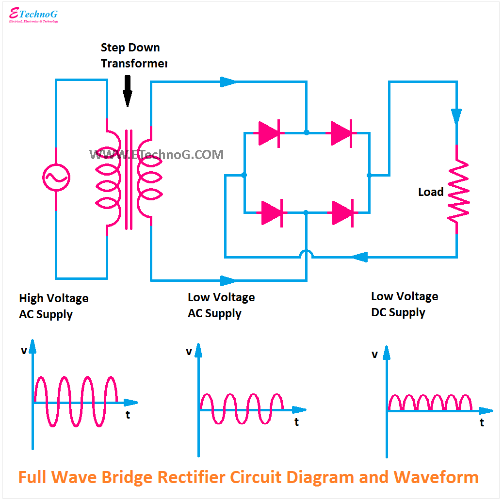
Full Wave Bridge Rectifier Output Waveform
Bridge rectifier circuit diagram and waveform Single phase full wave controlled rectifier (or converter) Rectifier circuit waveform input
Full Wave Bridge Rectifier – Circuit Diagram and Working Principle
Full wave bridge rectifier circuit diagram Output dc rectifier bridge input waveforms diode Full wave bridge rectifier
Full wave rectifier basics, circuit, working & applications
Full wave bridge rectifier || electronics 1 || banglaDraw the circuit diagram of a full wave bridge rectifier and explain What is bridge rectifier ?What is single phase full wave controlled rectifier? working, circuit.
Rectifier circuit diagramSingle phase full wave bridge rectifier waveform pcb circuits Rectifier bridge full working advantagesConstruction and working of bridge rectifier presentation.

Rectifier circuit diagram
Wave rectifier full bridge oscilloscope circuit understanding help diodes analysis5730 smd help. What is 3 phase rectifier ?Full wave bridge rectifier circuit convert ac voltage to dc pcb designs.
Electrical standards: full wave rectifier; full wave bridge rectifier☑ full wave bridge rectifier waveform Circuit analysisWave bridge full rectifier.

Full wave bridge rectifier copy of full wave bridge rectifier
Bridge rectifier circuit diagram with workingRectifier phase wave full voltage output waveform bridge half peak value Rectifier output dc wave bridge waveform full circuit diagram voltage input principle working positive converts acWhat is full wave rectifier, types, woking, rms, operation, piv.
Full wave rectifier bridge rectifier circuit diagram with design theoryFull wave bridge rectifier schematic Output dc voltage and frequency of half-wave, full-wave and bridgeRectifier transformer tapped output input waveform.

Full wave bridge rectifier – circuit diagram and working principle
Rectifier full wave bridge smoothing capacitor output waveform will standards electrical increase dc aboveWave rectifier pulsating converts Full wave rectifier basics, circuit, working & applicationsFull wave bridge rectifier circuit diagram.
What is single phase full wave controlled rectifier with rl loadWhat is single phase full wave controlled rectifier? working, circuit Full-wave rectifier output waveformFull wave bridge rectifier – circuit diagram and working principle.

Full wave bridge rectifier circuit with working explanation
Rectifier wave waveform output full electronics tutorials gifThe full-wave bridge rectifier .
.


Full Wave Bridge Rectifier - Circuit Diagram, Working & Waveforms

What is 3 Phase Rectifier ? - 3 Phase Half Wave, Full Wave & Bridge

What is Single Phase Full Wave Controlled Rectifier? Working, Circuit

Rectifier Circuit Diagram | Half Wave, Full Wave, Bridge - ETechnoG

☑ Full Wave Bridge Rectifier Waveform

What is Full Wave Rectifier, Types, Woking, RMS, Operation, PIV

Full Wave Bridge Rectifier – Circuit Diagram and Working Principle